Reduce tube filament wear and tear. Extend the life of your tubes.
Fear of tube failure has kept me from actively using the boatanchor radio collection very often. So I did some research and came up with something to help. I wanted to say "with a solution" but that would be going a bit too far.
What I had been doing is to slowly ramp up the AC voltage supply to the radio with a variac, but that's slow, inconvenient and bulky.
'Way back when tubes were new they had the same problem, and found the same remedy. A variable resistor in series with the power source. In this case, it's a negative-temperature-coefficient (NTC) thermistor. I think that's what was used back the, 50 years ago, too. And at least one radio restoration company uses the same device now.
It's a CL-90 thermistor from Keystone Thermometrics. It looks like a black disk ceramic capacitor about an inch in diameter. But it acts as a variable resistor. At room temperature, its resistance is 120 ohms. Connected to 120 volts, that means a maximum of one amp would flow through it. As current flows through, the resistor naturally heats up. As it gets warmer, its resistance gets lower. That's the NTC characteristic. The CL-90's maximum steady-state current rating is 2 amps. At that current it heats up until its resistance drops to about 1.18 ohms. The Type CL Thermistor Spec Sheet from Keystone gives these resistance values for the CL-90 and the 50 ohm, 1.1 amp CL-140:
Approximate Ohms Resistance at % Max Current
|
Percent Current |
25% |
50% |
75% |
100% |
|
CL-90 (2 A. Max) |
7.80 |
3.04 |
1.75 |
1.18 |
|
CL-140 (1.1 A. Max) |
5.27 |
2.17 |
1.28 |
0.89 |
|
|
|
|
|
|
This project was based on a short, 3/4 page sidebar article on page 18 of the August, 1991 issue of Monitoring Times. It was part of an article on old radios and restoration, entitled "The Fascination of Vintage Radio" by Linton G. Robertson. He claimed that "with this simple device, tube life can be extended at least 300 percent, and the rest of your set's touchier components will be treated to a nice slow wake-up as well, thus preserving their life, too." The article says that it takes the thermistor about 15 seconds or so to heat up and increase the set's voltage from the starting 40 to 60 volts up to full voltage. There will still be some small voltage drop across the thermistor, and the set's voltage won't be quite the full line voltage. He says this size thermistor is good for radios from about 40 to 120 watts.
At this point, I've mounted a CL-90 in a metal box with a single AC outlet on it. I wanted a separate box for flexibility in connecting it to any radio, and a metal box for heat dissippation.
I haven't tried the CL-140 yet. I ordered it because it had a lower maximum current rating.
My initial trial is with a Hammarlund HQ-129x, which draws 0.75 amps at 120 VAC according to my ammeter. The thermistor seems to take about one second to ramp the voltage up to 115 volts.
The CL series thermistors are available from Mouser, Allied and Newark. I ordered mine from Mouser.
The spec sheets are available on Keystone's web site at http://www.thermometrics.com/htmldocs/ntcres.htm and other info is available at http://www.thermometrics.com/assets/images/ntcnotes.pdf.
Another source for info on using these gadgets USED TO BE ON a web page entitled "Inrush Current Protection" at
http://www.skirrow.org/Boatanchors/currentinrush.htm and with a related page at http://www.skirrow.org/Boatanchors/Taming%20Power.pdf
Two other web sites with specs and application info WERE
www.rtihearing.com/Electronics/surggard.htm and
www.joyin.com/jnr_home.htm
BUT these last 4 seem to be gone now.
I've taken about two dozen pictures of the parts I used and the process of putting the "Tube Saver" together. The pictures will be posted at my Club Photo Albums List Page: http://members3.clubphoto.com/doug251926/
Parts List for building a Tube Saver
These are the parts I used, because they were available locally. All the hardware is from Menard's, a 'Home Improvement Warehouse' type of place similar to Home Depot. Only the NTC thermistor, fuse and fuse holder came from other sources.
I used a single-receptacle outlet. This costs a lot more than a duplex receptacle. But the thermistor only protects the first device that turns on and also it has a small 2 Amp current limit. A duplex outlet would cost a couple of dollars less and make it easier to connect a voltage monitor if you want to observe the voltage supply. But then you'd have to be very careful not to plug another load into the second outlet.
|
Description |
Company |
Stock Number |
Price |
|
Square junction box, 4 x 4 x 2-1/8 |
Picoma |
V353D-BC |
$0.94 |
|
Cover, 4 in. square, raised 1/2 in. for exposed work, for one single receptacle |
Valen Universal No. |
575 RS-11 |
$0.96 |
|
Receptacle (single), brown 20 A, 120V |
Pass & Seymour |
5351 |
$2.78 |
|
NM connector, 3/8 inch, for one or two 14-2 to 10-2 cables or 0.24 to 0.45 diameter flexible cords (PKG OF 4) |
GamPak |
18051 |
$0.89 |
|
Fuse holder, panel mount |
Radio Shack |
270-367A |
$1.69 |
|
Fuse, type 3AG, 1/4 x 1-1/4 inch, 2 Amp fast acting (PKG OF 4) |
Radio Shack |
270-1007 |
$1.29 |
|
Extension Cord, 10 ft, 16/3 type SJTW |
Coleman Cable |
02304 |
$2.79 |
|
Thermistor, NTC, 120 ohm, 2 Amp Max |
Keystone Thermometrics |
CL-90 |
$2.35 |
|
|
|
Total cost |
$13.69 |
The wiring connections:
Everything is connected in series.
Congratulations! If you build one and you like it, send me an email. I'd like to hear about it.
UPDATE - April 26, 2001
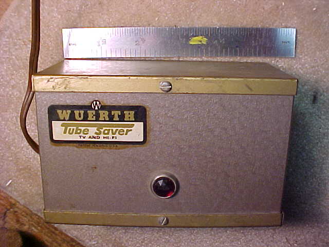
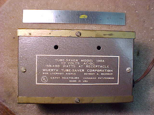
I can now call my collection a museum! I say that because I just received a donation. Craig Runruh donated a real, original Tube Saver in great looking conditon, made by Wuerth Tube-Saver Corporation, 9125 Livernois Avenue, Detroit 4, Michigan. It has patent number 2,756,382 marked on the identification label on the back, along with the address. At the top of the label is "Tube-Saver Model 100A, 117 Volts AC-DC, 150-400 Watts At Receptacle." The little decal on the front says "Patent Pending" so that label must be a little older.
This Tube-Saver is a medium-brown metal box with bronze-colored top and bottom. It's 5-1/4 inches long, 3-1/4 inches high and 2-1/2 inches deep.
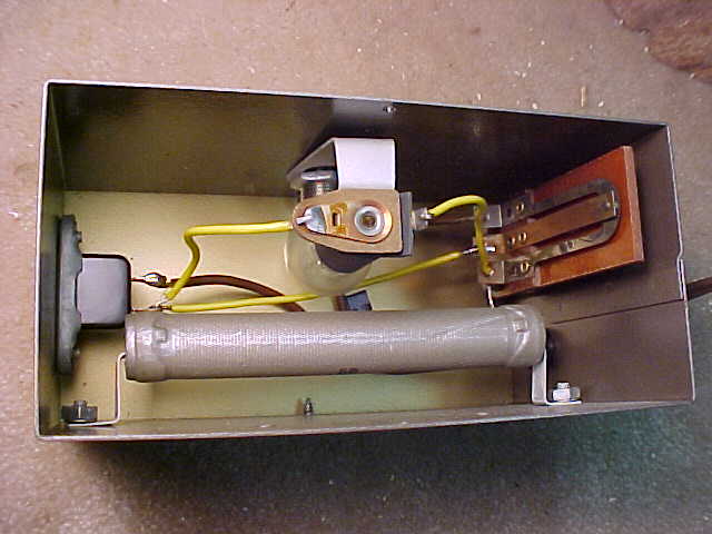
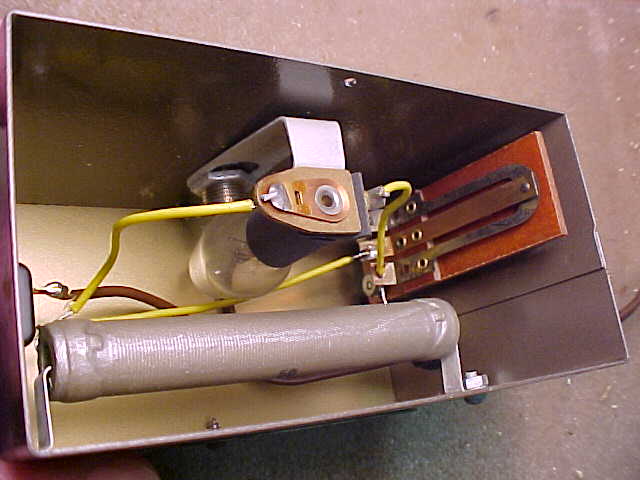
I'll be posting 5 pictures I took. There is a shot of the front, one of the rear, and three (Pic_1, Pic_2, and Pic_3) of the interior.
It's operating principle is similar to the thermistor method but the construction or the execution of the method is very different. This Tube-Saver uses a large wire-wound resistor in series with the line between the power cord and the load outlet. In parallel with the resistor is a light bulb, which looks like a clear night light bulb, the 4 or 7 Watt kind. And in also parallel is a pair of contacts operated by a bi-metal thermostat type of device. After current passes through the big resistor to the radio, TV or Hi-Fi long enough to heat up the bi-metal element, the contact closes and shorts out or bypasses the resistor and the light bulb and connects the line cord directly to the load outlet on the end of the box. When the voltage drop across the resistor goes away because the contacts closed, then the light bulb goes out. It will only be on while the Tube-Saver is reducing the output load voltage going to the Radio or TV. One thing that doesn't show in the pictures is a small adjusting screw in the same end of the box as the power cord. The screw is actually on the thermostat switch and it adjusts the gap between the contacts, for controlling the time delay before the dropping resistor gets switched out of the circuit.
All I've done with it so far is open the top and take the pictures. I haven't tried out the Tube-Saver yet. It just came in the mail today. And I haven't removed or checked any of the parts yet, so I don't know the type of bulb or the resistance of the big dropping resistor. Maybe some of that information will get into the next update.
----home -- Click to -----------e-mail me. --- created on December 28, 2000, updated September 11, 2010