Part 5 of a series on antennas appears in Radio-Electronics Magazine for June, 1983 on page 83. Its title is "All About Loop Antennas for VLF-LF."
I'll reproduce the text, but there are several illustrations that I can't duplicate. It would be worthwhile to find yourself a complete copy of the article. My copy is pretty poor and I can't even tell what's in many of the figures!
Added December, 2001 - I have recently found a better copy of this article and scanned it, complete with separate scans of the graphics. Go back to the Short Wave Radio Page and look for the link.
Perhaps the most important difference between loop antennas and the whip antennas that we have previously discussed is the loop's directivity. (The vertical whip is, of course, omni-directional and cannot indicate the direction from which a received wave comes.) Before we can talk more about this directive property, we have to take a look at how an electrical signal is induced in the loop by a passing electromagnetic wave, and at some general electrical characteristics of loop antennas.
Loop antenna characteristics
A current is set up in a loop antenna by a changing magnetic field. (That current is equal to the integral of the electric field that is induced around the loop.) The sensitivity of a loop is directly poroportional to the loop area and to the number of turns in the loop. It is, in general, inversely proportional to the wavelength of the signal. Small receiving loops for 60 kHz (WWVB) require a preamplifier with a voltage gain of 30 dB or more to make them comparable in performance to a small active whip antenna. [Ed. Note: notice the key word 'active' here!]
The inductance of the loop winding itself makes loop antennas frequency-sensitive. Because of that, it becomes difficult to make such antennas with wide-band characteristics. To increase the sensitivity of a loop, multiple-turn coils are used at the VLF-LF range. However, the distributed capacitance of the windings acts with the loop's inductance to decrease the antenna's frequency response. That however, is not always a disadvantage. The frequency selectivity of a loop winding is often an advantage in that it can provide for rejection of out-of-band signals (in other words, it can form a sharply tunable antenna system). Loop antenna systems seldom have intermodulation-distortion problems because of their lower sensitivity, lower impedance level, and better selectivity.
Directivity of loops
Perhaps the most significant and valuable property of loop antennas is the fact that they can be used to determine the direction of an arriving signal. Let's look at how they can do that. Consider a loop and a vertically polarized passing electromagnetic wave as shown in Fig. 1-a. {SORRY!] A voltage will be induced in the vertical members of the loop, but none in the horizontal ones. If the voltages induced in each vertical member are the same (as they would be if the plane of the loop were perpendicular to the direction of travel, Z, as shown), then no current will flow. [editor's note: the advancing wave front hits the entire loop broadside, all at the same time, so there is no conductor cutting a magnetic line of force.] However, if the plane of the loop is parallel to the direction of travel of the oncoming wave, as shown if Fig. 1-b, then the wave will reach one side of the loop before the other, the total voltage around the loop will not be zero, and current will flow. [transformer action!] The voltage induced in the vertical members is proportional to the height of the loop, and voltage difference between the vertical members is proportional to the width of the loop. Therefore, the voltage around the entire loop is proportional to the product of its height and the width - that is, its area.
Another way of reaching the same conclusion is to say that the voltage induced around the loop is proportional to the rate of change of the magnetic-flux linkages through the loop. Then it is obvious that the area of the loop is the controlling factor, and the loop will receive the most signal when its plane is normal (perpendicular) to the magnetic field (H) of the oncoming wave (or in the same plane as the direction of travel of the oncoming wave).
Direction-finding shortcomings
The directional properties of loop antennas that we have just described permit you to null out interference or to obtain a broad peaking of a signal merely by rotating the loop. However, loops, though they are often used because of their relative simplicity, are not ideal direction-finding antennas.
Loops cannot distinguish between signals that arrive from opposite directions (for example, north and south). Another drawback is that trying to determine the source of a signal that arrives at an angle different from that of the ground wave (not exactly head-on) will usually result in an error. Ground waves themselves frequently arrive "tilted." That tilting is often due to the magnetic effects of such things as the steel I-beams of buildings (which distort the boundary conditions even for close-in ground wave reception). One way tht the problems caused by downcoming ("tilted") waves can be reduced is by using an Adcock antenna. We won't discuss that antenna in any detail except to say that it operates by canceling out voltages induced in its horizontal members. A third problem that loop antennas have in direction-finding applications, especially at low frequencies, is due to the antenna effect. The antenna effect is seen when a direction-finding antenna acts like a simple, non-directional one. Loop antennas, when used at low frequencies, are subject to that effect because their size is aonly a fraction of a wavelength, and they pick up interference from a signal derived from the electric, rather than the magnetic, field. A loop's symmetry should ideally cause that signal to be cancelled out, but in real systems the effect is often the source of problems.
Resolving those problems
If you were to turn a loop antenna through 360 degrees and observe the strength of the signal received, you would obtain a reception pattern that looked like a figure-8. Such a pattern leaves you with a 180 degree uncertainty as to which direction the signal is from. That uncertainty can be resolved by using a whip antenna in conjunction with the loop to cancel one of lobes of the figure-8 pattern. That is done by coupling the output of the vertical antenna to the loop so that the voltage induced in the loop by the coupling is 90 degrees out of phase with the voltage the passing wave induces in the vertical antenna. Figure 2 [in the magazine only] shows the cardioid directional pattern that results from combining the figure-8 with the omnidirectional pattern from a whip. The sense of the incoming signal is usually determined by rotating the loop to cancel one of the lobes of the figure-8. In practical systems it is necessary to provide some phase- and amplitude-balancing between the two antennas.
To reduce the antenna effect that distorts the loop's directional pattern, and to obtain the best performance (in terms of detecting sharp nulls and uniform amplitude-peaks as the loop is rotated), the loop should be mounted within an electrostatic shield. That arrangement balances the loop by making sure that all parts of it will have the same capacitance to ground. That shield or cavity also protects the loop from the induction field created by nearby disturbances. The induction field refers to the electric and magnetic fields in the immediate vicinity of an antenna. Those fields decrease rapidly in strength with distance, and the induction field is usually ignored (and the radiation field is all that is considered). However, wires and other metal objects near the loop can take energy from a passing wave and produce induction (and radiation) fields that can induce spurious voltages in the loop.
A shield over a loop antenna (one type of shielded loop is shown in Fig. 3 [but not here!] ) will not appreciably decrease the amount of magnetic flux that passes through (and links with) the loop when a wave goes by - as long as it does not form a complete (shorted to itself) turn. An insulated segment or gap is always left in the shield so that it does not become a shorted turn. Without the gap, the shield would form a shorted turn and it would reduce the magnetic field linking the loop so that no signal could be received by the internal wire(s). With the insulated segment or air gap, alternating currents can be induced in the metal shield (but no current will flow), and voltages will be induced in the internal wire(s). Some experimenters have wound loops inside slit Hula-Hoops and then shielded them by wrapping the outside with aluminum tape, leaving a gap in the tape at the top of the loop. Ferrite-core loops (which we will discuss shortly) are usually mounted axially in a trough or U-shaped channel (with the top and ends open to prevent a shorted turn) for electrostatic shielding.
A method for making a square box-frame loop is shown in Fig. 4 [sorry again]. A long length of U-channel is formed into a box frame by cutting slots into the side of the channel and then bending the material. [The bottom of the U is toward the inside of the box. The slots are cut in the "upright" arms of the U.] A small gap with a plastic insulator in it is left at the top of the frame; the insulator holds it together and prevents it from forming a shorted loop. The coil winding is supported on plastic foam, just below the outer edges of the U-channel.
Winding loops
The distributed capacitance of the loop may, especially at low frequencies, cause the current to vary at different points on the loop and cause deviations in the directional pattern. A technique for reducing the distributed capacitance of the loop windings is to make the loop in a mobius form. A mobius loop is one where the coil is "twisted" so that (except at the start/finish point where the wires cross) all the "even-numbered" turns are adjacent to one another, with the same being true for the "odd-numbered" turns. The distributed capacitance of the mobius-type antenna shown in Fig. 5 is about one-half that of the antenna illustrated in Fig. 4 - even though both contain the same number of turns. The mobius-wound antenna also has a wider bandwidth.
Effective length
When we discussed active-antenna systems [in a prior article in the series, and which I don't have], we frequently mentioned the effective length of an antenna (often referred to as effective height). We can also talk about the effective vertical length of a loop antenna. An approximation for computing the effective length, LL, of loop antennas is
LL = (2*pi*n*A*Mu)/(wavelength)[Eq. 1]
Where wavelength is in meters; n = the number of turns in the loop; A = the cross-sectional area of one turn in square meters; Mu = the effective permeability of the core material ( = 1 for air core); and wavelength = (3*(10**8))/(frequency in Hz). [That's wavelength = three times ten to the eighth power, then divided by frequency.]
Small-size ferrite-core loop antennas
It is often useful to consider the smallest practical size of loop antenna that can be used, say for reception of signals such as those from WWVB at 60 kHz. Using a ferrite core increases the effective permeability of the core and, as you can see from equation 1, that increases the effective length. Ferrite cores are available commercially in several different permeability ranges. Figure 6 is a chart that illustrates the effective permeability of a ferrite rod compared to the bulk permeability of the ferrite material.
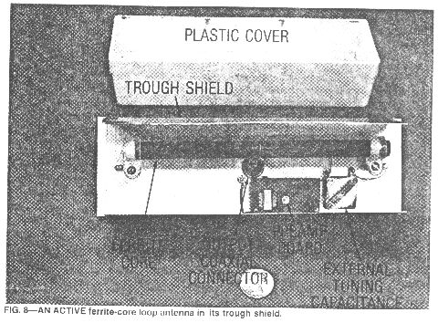
The whole idea of using a ferrite-rod core is to increase the magnetic flux density through the loop. For the maximum effect, you want to have as much of the core exposed to the winding as possible. Compact, multiple-layer coils in the center of a long core-rod are never as sensitive as a single-layer coil that covers almost the whole length of the rod. Unfortunately a long coil has a problem in that the distributed capacitance of the coil winding is quite high, and the Q of the long coil will not be as good as a coil with a better "shape factor" (smaller length-to-diameter ratio). To maximize the coil's sensitivity to the magnetic field in space, the product of the number of turns and effective permeability of the rod should be as large a number as possible. From Fig. 6 it can be seen that the whole length of the rod should be used to maximize the effective permeability. Another factor to consider is the effect that the ferrite material used has on the Q of the coil. (At low frequencies, the maximum Q that can be obtained depends on the core material, its size, and the signal frequency.) Figure 7 describes the effect on Q for an 800 Mu bulk-ferrite-material rod that measures 1/2 x 7 x 1/2 inches. It also describes the antenna's response with and without external capacitances added. The winding properties of the ferrite-core loop are included in Table 1, and Fig. 8 shows the ferrite-core loop-antenna itself.
Comparing loops
The comparative properties of a ferrite-rod antenna and the two air core box frame loops (shown in Figs. 4 and 5) are shown in Table 1. The scramble-wound box loop, which is in a slightly smaller U-channel, has a higher winding capacitance that results in a resonant frequency of 180 kHz. The mobius flat-wound loop has only half the winding capacitance and almost the same inductance. That results in a higher resonant frequency of 275 kHz. Both of the air-core box loops are intended to be operated in the wideband mode with no external tuning-capacitance. [editor's note: this is the only place I've seen this "no tuning capacitor wideband mode" mentioned.] The mobius box-frame loop has exceptionally deep nulls of 40 dB or more in the 60-kHz to 100-kHz frequency range. The ferrite-rod loop is intended for fixed-frequency use (tuned to 60 kHz with an external tuning capacitor) for WWVB reception. Similar ferrite loops (where the loop coil and housing is different for each frequency band) that cover a wider frequency range are available commercially from several sources.
For an untuned box-loop, the upper-frequency limit is determined by the self-resonant frequency of the coil and its distributed capacitance. The effective length is greatest at that point, and it decreases by a factor of 10 or so at the 10-kHz low-frequency end. The box loop can also be tuned by placing a tuning capacitor in parallel with the loop coil. That will increase the Q, but a preamplifier with a higher input impedance will be required. The best power transfer from the loop coil to the preamplifier is usually obtained when the loop impedance and the preamplifier input impedance are in the same range - which is not at highest Q. In designing loop antennas there is always a compromise to make between selectivity and sensitivity. An untuned loop with a rather broad self-resonant frequency peak (which is the case for the flat mobius-coil box-loop) provides the best sensitivity and also the deepest nulls of the antennas compared in Table 1.
Balanced Loops
As we discussed previously, to obtain the best null performance, loop antennas should be operated so that the capacitance between the antenna and electrostatic shield is the same at all points along the loop. With a single winding that's a problem, since one end of the winding has to be grounded in some way. A loop with a center-tapped winding is often used together with a preamp with a balanced input, but there is a better way of winding loops on long ferrite rods that also reduces the inductance of the whole winding and results in a single-ended termination for the loop.
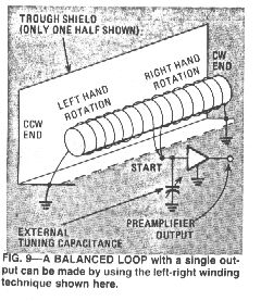
The technique developed by the U.S. Army Signal Corps many years ago, involves making right-hand and left-hand-sense windings starting at the center of core. The resulting loop, shown in Fig. 9*, still has opposite-phase nulls off opposite ends, but now has excellent electrostatic symmetry with respect to the trough shield. (The ferrite core loop discussed earlier was a balanced loop.) The sensitivity of this coil is about the same as that of a coil wound in a single direction from one end to the other, but the inductance is reduced, resulting in a higher self-resonant frequency. The termination point in the center of the core practically eliminates induction-field noise pickup, even with a single-ended preamplifier system. When winding a coil with a relatively large number of turns, it is advisable to check the winding for inductive balance because the ferrite core material may not be uniform from end to end. Another factor contributing to non-uniformity is that it is difficult to wind a perfectly spaced coil by hand. That is why the figures indicating the number of turns on each side of the antenna described in Table 1 are different.
To tune the balanced loop coil arrangement shown in Fig. 9* to resonance at 60 kHz, a fixed capacitor of about 500 pF can be placed in parallel with a small variable capacitor of up to 350 pF (and the 330 pF distributed capacitance of the coils). That allows the total capacitance to be set to about 1000 pF - the capacitance required for resonance with the 6.89 mH inductance indicated in Fig. 7.
Balun method
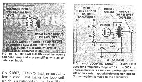
Another technique for making the capacitance of a single-winding loop symmetric with respect to the electrostatic shielding is to employ a toroidal balun (BALanced-line to UNbalanced line) transformer between the loop winding and the preamplifier. That technique is illustrated in Fig. 10. The balun is used with the air core box loops shown in Fig. 4, which have no center tap on the loop windings. The trifilar-wound transformer consists of about 30 turns of No. 30 insulated wire-wrap wire twisted 6 to 8 turns-per-inch and wound on an Amidon (12033 Otsego St., North Hollywood, CA 91607 [www.amidon.com I think] FT82-75 high-permeability ferrite core. That makes the loop coil, which is a balanced source, look like an unbalanced source to the preamplifier. Baluns can also be used with ferrite core antennas wound in a single direction (instead of the right-left method of Fig. 9).
Loop antenna locations
Loop antennas are much less sensitive than small whips, but they have the advantage of having more selectivity as well as having directional null- and peaking- properties. It's a good idea to place a loop in the attic of a house well away from the electrical appliances and power lines, and to keep it away from major steel structural members (which distort the local magnetic field).
High-gain preamplifier
When designing an active whip antenna, we considered the whip to be a voltage source with a high internal impedance requiring current amplification, and (to reduce attenuation due to a mismatch) we wanted the preamplifier also to have a high input impedance. However, with a loop antenna, which is considered to be a low-impedance current source, we want a low impedance voltage amplifier.
Almost all LF loop antennas will require a preamplifier with a voltage gain on the order of +30 dB. Low-noise performance is more important here than with whip antenna preamps because of the lower signal levels at the loop terminals. There is a great varietyu of circits possible, but one of the simplest uses a power-FET or VMOS-FET like the one shown in Fig. 11. That preamp should be mounted directly at the terminals of the loop in a weatherproof shielded box or inside of a trough shield (with the balun transformer, if required). The output of the amplifer is fed (through a coaxial cable ) back to the same receiver coupler that we used with the active antennas described in previous articles. The gate bias voltage divider trimmer potentiometer is adjusted so that the operating current of the receiver coupler is about 40 mA. The VMOS transistor used can be the Siliconix VN10KM. You can also use an ITT BS170 - which has properties similar to those of the VN10KM, but a different pinout. The series resistor for the gate bias, about 15,000 ohms, is chosen to approximately equal the reactance of the loop coil at the highest or cutoff operating frequency. If a tuned loop coil with higher Q is used, then the value of the resistor should be increased in value to 100,000 ohms or so. The output transformer can be the primary winding (about 200 or 600 ohms) of a subminiature or ultraminiature audio transformer. The secondary can be left open for operation up to the 500 kHz region. At higher frequencies a bifilar toroid - such as the one wound on an Amidon FT50-75 core for the wideband active whip preamplifier - can be used as an output transformer. The preamplifier will have a voltage gain of about 30 dB when driving a 50 ohm load at the receiver coupler.
Bench testing loops
You can evaluate the resonant frequency of a small loop antenna system by connecting a coupling coil and a 50 ohm load resistor in parallel as a termination at the end of a coaxial cable from a signal generator. For low frequency testing (below 500 kHz) the coil can be a 1-mH pi-wound RF choke. The probe is brought very close to the loop under test to inject a small amount of signal by magnetic or inductive coupling. The output from the loop and/or a suitable preamplifier are then observed (either on an oscilloscope or a receiver) as the signal generator is tuned over the desired frequency range. The coupling sensitivity of both the probe coil and the loop will decrease at lower frequencies. This simple magnetic probe will allow you to obtain a good idea of the loop resonance and its general performance. You can also estimate the loop inductance by placing known capacitors in parallel with the antenna and then observing the response. The coil's distributed capacitance can be estimated by computing the difference between the resonant frequencies of the loop with and without the added tuning capacitance.
* for Fig. 9, take the piece of wire to wind the loop with and fold it in half. Lay the wire on a table in a long, narrow V layout. Set the rod core on top of the wire close to the apex of the V and put a dab of glue there to hold it. Then roll the rod along the wire so that the wire winds up around the rod and expands the coil toward both ends at the same time. That's the bidirectional coil shown in Fig. 9.
[Note: I hope that MS Word's spell checker caught all of my multitudinous typing errors! If not, SORRY!]
------home ------------- --------- updated October 12, 1999 & December 16, 2001