After reading the SuperRadio FAQ and the reviews and other articles I could find, I decided to order the service manual for my Superadio III. I've had it for about 5 years but rarely used it. I didn't try it out very thoroughly right after I got it or I would have tried to exchange it for another one. When tuning FM it seems very poorly aligned, as though there is a very big dip near the middle of the passband. The audio quality seemed distorted over most of the area of the tuning dial where I could receive the station I was tuning.
Then I happened to accidentally run into several very favorable comments about the radio while reading some internet articles, so I got it out again. I opened it up and tried tuning or aligning it by ear, but it didn't help much. I didn't expect it would, though. I've aligned FM radios before and even with a sweep generator and oscilloscope hooked up, it wasn't especially easy.
Since I do have a collection of older test equipment including sweep generator and scope, I bought the manual to make a better try. I hope that publicizing the instructions will help others improve the dial calibration error troubles.
The manual cost $5 plus tax, and shipping was $4.95. So it cost me about $2 per page for the 5 page manual. That includes the cover and page 2, which is a safety check for AC line voltage leakage at the power transformer frame and the volume control frame. Page 3 is the parts list but it only gives GE stock part numbers. Page 5 is the schematic wiring diagram. It's a 3-page fold-out. There is no parts placement layout diagram! But don't give up hope - see below. I ordered the manual by phone from Thomson Consumer Electronics, (502) 491-8110. The manual is marked with the radio model number 7-2887A and is apparently their publication number SM72887A. Manuals are available from Thomson so please don't ask for a copy of mine. [updated March 16, 2002]
[November 13, 2002 - Thomson no longer sells the SR3 service manual, so I scanned mine and posted it here (as a DjVu file). The original schematic is larger than 11x17 paper so I had to scan it in multiple pages. There are 4 and there is a substantial amount of overlap between them. Keep that in mind when you look at it or some parts will seem to be duplicated. Click here to view ge_sr3_ScvMan.djvu (71k).
NOTE: It's posted as a DjVu file, which requires a free browser plug-in available from http://www.lizardtech.com/ in order to view it.
===============================================
Second Note: A free (shareware) PDF generator has enabled me to post the service manual in PDF format as of September 15, 2005.
Here it is: GE SR3_Svc_Man.pdf - It's about 300kB.
===============================================
I've gone through the alingment procedure and it did help some distortion I had in the FM section. I hadn't really noticed any problem with the AM, except for the tuning dial being rather inaccurate. But I thought I would publicize the procedure for it. It does give the RF alignments, and the setting for R1. R1 sets the maximum and R3 sets the minimum tuning voltage that the main tuning potentiometer R2 applies to the six Varactor tuning diodes. The AM alignment did help the dial calibration quite a bit, too.
NOTE: This is all the technical information from the manual! There isn't any more.
Some, but not all, part identifications are printed on the circuit board. BUT I can't find identification markings for the transformers! And there is no layout diagram. I made a simple
sketch of the parts layout, and an ASCII table showing the parts layout. It's fairly accurate and should be helpful, but it's only a guide.I now have a 154 KB photograph of the circuit board, which I've annotated with the locations needed for alignment. This 154 KB picture was added on May 1, 2000. However, I haven't found L4 and I'm not positive which are C13 and C26.
Also unmarked on the PC board is TP1. But the schematic shows TP1 to be the junction of C15, C21, R33, L3 and the base of Q2. With R33 at the top of the board, I connected the signal generator to the lead on the left end of R33.
On September 4, 2000, Mike from Rome, NY told me about another SR3 PC Board layout graphic.
So I asked for permission to reproduce Paul's SR3 PC Board graphic here. This is his email response:
No problem, so long as you acknowledge the origin.
The main diagram was originally drawn in the USA by Christopher King &
snail-mailed to me here in England. I scanned the drawing into my
computer, tidied up the graphics & added a couple more items not
included on the original.
All the best.
-- Paul Sexton Paul's Radio Museum
http://www.paulplu.demon.co.uk/radio/
But, please note that my pictures show T8 and T9 interchanged from his depiction. Also note that T9 is part of the AM circuitry, and T8 is in the FM Discriminator section. So it won't be hard to tell which is which. T9 will only affect the AM, so tuning it during an FM alignment won't have any effect. And likewise with T8, which won't have any effect on AM reception. If someone sends positive, confirmed information on which layout is right, I'll make corrections here.
Also see
GE Superadio FAQ Appendix A: Repairs and Modifications at http://www1.shore.net/~dmoisan/faqs/superradio/gesr_app_A.html#power for more information and tips.Here are the alignment instructions from the manual:
GE Superadio III model 7-2887A Alignment Procedure Instructions
Connect your output meter across the speaker terminals. Use the minimum possible signal generator output for the AM alignment so that the AGC doesn't mask the changes is level.
AM Radio Alignment - RF Radiated signal (not directly connected to radio)
|
Step |
Generator Frequency |
Radio Dial Setting |
Indicator |
Adjust |
Remarks |
|
1 |
455 kHz |
Low End |
Output Meter Across Speaker |
T4, T5, T6, T9 |
Adjust for maximum. |
|
2 |
1640 kHz |
High End |
C37 |
Adjust for maximum. |
|
|
3 |
520 kHz |
Low End |
L5 |
Adjust for maximum. Repeat steps 2 and 3 for Band Ends. |
|
|
4 |
1420 kHz |
Tune to Signal |
C8, C30 |
Adjust for maximum. |
|
|
5 |
600 kHz |
Tune to Signal |
L6, T10 |
Adjust to obtain maximum output. Repeat steps 4 and 5 until no further improvement is noted. |
FM Alignment -
High side of FM Sweep Generator connected thru 5 pF capacitor in series with 68 ohm resistor to TP1 for steps 1 and 2. Note: for TP1, I had to use the (left) end of R33 (see my chart).- RF Radiated signal (not directly connected to radio) for steps 3 to 6.
|
1 |
10.7 mHz |
Low End |
Scope at TP4 (U1, Pin 2) |
T1, T2, T3 |
Adjust for maximum gain and symmetry. Repeat as necessary. |
|
2 |
10.7 mHz |
Low End |
Scope at TP5 (U1, Pin 8) |
T7, T8 |
Adjust for symmetrical S-curve using strong input signal. |
|
3 |
109.0 mHz |
High End |
Output Meter Across Speaker |
C26 |
Adjust for maximum. |
|
4 |
87.2 mHz |
Low End |
L4 |
Spread or compress coil windings to raise or lower frequency. Repeat steps 3 and 4. |
|
|
5 |
108.0 mHz |
Tune to Signal |
C13, C17 |
Adjust for maximum. |
|
|
6 |
88.1 mHz |
Tune to Signal |
L1, L2 |
Spread or compress coil windings to obtain optimum alignment. Repeat Steps 5 and 6. |
Note: Scope used must have at least 50 MV/CM sensitivity and sweep generator at least 200 mV output.
L7 Alignment
1. Connect a frequency counter through a 150K ohm resistor to the cathode of D1.
2. Adjust L7 for 3 mHz to 3.5 mHz.
R1 Alignment (tuning voltage)
Set band switch to FM position and AFC switch to off.
1. Connect a high impedance voltmeter to junction of R2 and C7.
2. Adjust R1 for 9.4V to 9.6V.
AFC Alignment
Set radio frequency to 98 mHz and AFC switch to off.
1. Measure DC voltage at junction of C5 and S2 (AFC Switch)
2. Connect voltmeter to junction of R45 and S2 and adjust R45 for same voltage as measured at junction of C5 and S2.
Parts Availability Info (added April 5, 2000) -
Wendell emailed asking about info from the service manual. He was looking for a part number for the 16-pin IF chip.
Quote:
I used to have a service manual but have long since misplaced it. My SR III has developed a problem specifically with either U1 or U2 (the IF chip) but I can't recall now which one it was. I do recall that the manual did identify one of the two IC chips in the radio and the one that was identified just happened to be the one that has since gone bad on me. The audio is terribly distorted until the radio warms up a bit. I managed to verify this by hitting the chip in question with some cold spray and sure enough, the audio went sour.
I would like to find out what the manual identifies that IC as by part number. I know that in the radio itself neither IC is identified by a standard part number but in the manual one of them did in fact have a common semiconductor number that I thought
was good to have for future reference. Little did I know at the time I'd need it later.
If you would be so kind as to let me know what the part number is I'd greatly appreciate it. I can then order the part and get my radio sounding pleasant again.
His next message:
. On the other hand, I guess I could try to order the chip directly from Thompson. In fact, I guess I should try that first just to see if they even have it.
End quote
I (Doug) asked Wendell to let me know what he found out about parts availability.
I told him that the service manual only give GE/Thomson part numbers, but that he could call Thomson and order it.
His email reply follows:
Quote:
The end result of my quest:
I checked Thompson Electronics' website (www.thompsontv.com) and found that they offer a parts research tool as part of their
"Replacement Parts" area.
I just filled out an online form describing the part in detail and I received a reply a day or so later giving me the cost of the part and terms of purchase (all orders have to be prepaid).
They sell the chip for $6 plus S&H is $5. I'd usually consider $11 for an IC of this type to be a bit steep but since I'm not likely to find it anywhere else, who's to say what's steep when there's no competition.
In any case, their service seems to fill the bill for those hard to find items found in GE/RCA products that Thompson services.
Thanks again for your time and help.
Del
End quote
Dial Stringing (added October 7, 2008)
I've had requests for help with re-stringing the dial cord. Does anyone have a good picture or a clear, easily understood diagram of how to do it? If so, and if you're willing to share it, pleas let me know. DON'T just email it though! I still use a slow dialup connection and most people's pictures and graphics are in huge files. I can help get the file size down to about 50kB or so before sending it.
----
home --- or --to Radio Page - Click to -----------e-mail me. -- October 7, 2008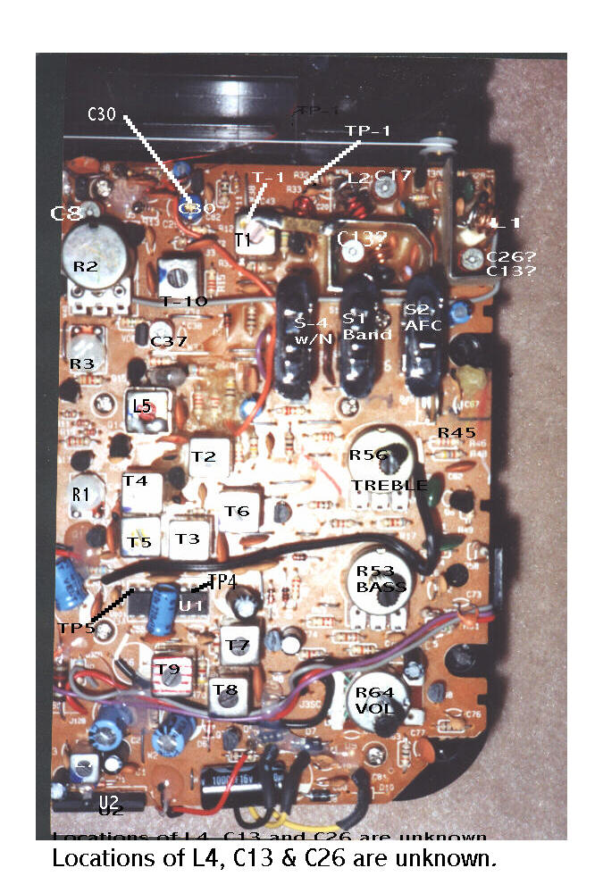